
1. Thermodynamics of Phase Transition: Cavitation vs. Flashing Fundamentals
In high-pressure liquid throttling (such as boiler feedwater recirculation, amine letdown, and offshore produced water choke service), differential pressure across the valve seat often exceeds 40 to 150 bar. When localized static pressure at the vena contracta drops below the fluid's vapor pressure (Pvc < Pv), liquid molecules vaporize into millions of microscopic vapor cavities. The ultimate fate of these vapor cavities defines the fundamental difference between two destructive phenomena:
- Flashing: When downstream outlet pressure remains below vapor pressure (P2 < Pv), vapor cavities persist and expand as a two-phase liquid-vapor mixture. Fluid velocity skyrockets, creating abrasive sandblast-like erosion that cuts smooth grooves into the valve body wall and downstream pipe.
- Cavitation: When downstream pressure recovers above vapor pressure (P2 > Pv), the surrounding liquid forces the vapor bubbles to collapse catastrophically. The implosion is violent and localized, generating micro-jets that attack valve metal surfaces.
2. Micro-Jet Destruction Dynamics: 1,000 m/s Micro-Jets & 1.5 GPa Local Shock Pressures
When an asymmetric vapor bubble collapses adjacent to a solid metal wall, surrounding fluid rushes into the cavity, forming an ultra-high-velocity micro-jet directed at the metal boundary. Laboratory optical measurements reveal:
Localized Shock Wave Pressure: P_impact = 1.0 to 1.8 GPa (10,000 to 18,000 bar)
Cycle Frequency: 10,000 to 100,000 implosions per second
No metallic alloy can withstand repeated cyclic stress of 1.5 GPa indefinitely. The impact fatigue ruptures grain boundaries, dislodging microscopic metal flakes and creating characteristic sponge-like pitted craters across valve plugs, seat rings, and cage walls.
3. Dimensionless Cavitation Indices: Quantifying Severity per IEC 60534
To determine required trim geometry, instrumentation engineers evaluate the Cavitation Index (σ):
Where:
• σ > 2.0: No cavitation risk; standard single-stage trim acceptable.
• 1.5 < σ ≤ 2.0: Incipient cavitation; hardened trims (17-4PH H1150M or Stellite 6) recommended.
• 1.0 < σ ≤ 1.5: Severe choked cavitation; multi-stage pressure letdown trim mandatory.
• σ ≤ 1.0: Full flashing regime; angle body with sacrificial liner sleeve required.
4. Multi-Stage Pressure Letdown Trim Engineering: The Series Resistance Principle
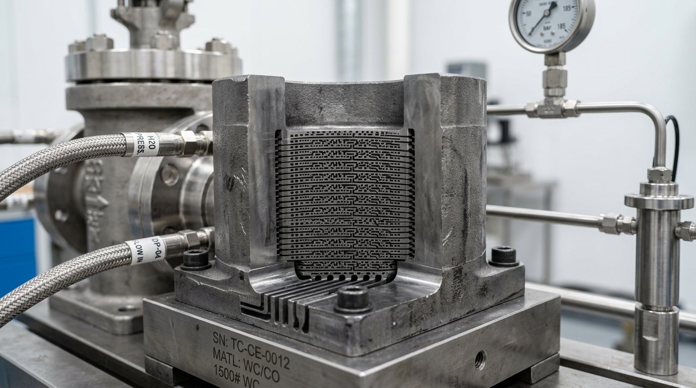
The only engineering method to completely eliminate cavitation is to ensure static pressure never drops below liquid vapor pressure Pv. TSV Series 8000 Multi-Stage Anti-Cavitation Trims achieve this through Series Resistance Breakdown:
P_vc(i) = P(i) - [ (ΔP_stage / FL²) ] > Pv for all stages i = 1, 2, ... N
By dividing a 90 bar total pressure drop across 4 concentric chambers, each individual stage experiences only 22.5 bar pressure drop. The vena contracta in every stage remains comfortably above Pv, preventing bubble inception entirely.
5. Flashing Service Valve Body Design: Angle Bodies & Expanded Pipe
Because flashing cannot be prevented if downstream process pressure P2 is below Pv, the engineering strategy shifts from prevention to deflection and wear containment:
- Angle Body Geometry: Fluid enters through the side and discharges straight down through the bottom, directing the erosive two-phase jet into the center of the downstream pipe rather than impinging against valve body walls.
- Expanded Outlet Gallery: Increasing outlet size (e.g., 4" inlet x 6" outlet) reduces exit velocity to below 10 m/s for liquids.
- Hardened Sacrificial Liner Sleeves: Replaceable Stellite 6 or 316L liner inserts protect the pressure-retaining body from fluid erosion.
6. Severe-Service Metallurgy Comparison Matrix
| Trim Material Specification | Hardness Rating | Cavitation Resistance | Corrosion & Temperature Limits |
|---|---|---|---|
| Standard 316 Stainless Steel (ASTM A276) | 180 – 210 HBW | Very Poor (Erodes rapidly) | Up to 450°C; standard process |
| 17-4 PH Double H1150M (UNS S17400) | 28 – 33 HRC | Moderate (3x vs 316) | NACE MR0175 compliant; up to 340°C |
| Stellite 6 (Cobalt-Base CoCr-A Hardfacing) | 40 – 44 HRC | Excellent (10x vs 316) | Resists galling up to 650°C |
| Tungsten Carbide with Ni Binder (WC-Ni) | 88 – 92 HRA (70 HRC) | Superior (40x vs 316) | Severe erosive slurry; avoid thermal shock |
7. Worked EPC Engineering Calculation: High-Pressure Condensate Letdown
| Process Parameter | Specified Value | Unit | Design Reference |
|---|---|---|---|
| Operating Fluid | High-Pressure Boiler Condensate | — | T = 145°C (293°F) |
| Inlet Pressure (P1) | 65.0 | bar a | High-pressure separator liquid level outlet |
| Outlet Pressure (P2) | 8.0 | bar a | Deaerator storage drum (ΔP = 57.0 bar) |
| Liquid Vapor Pressure (Pv) | 4.15 | bar a | Steam tables @ 145°C |
| Cavitation Index (σ) | (65.0 - 4.15) / 57.0 = 1.068 | — | Severe destructive cavitation zone |
Trim Stage Sizing:
ΔP_stage_max = FL² * (P_local - Pv) = 0.81 * (65.0 - 4.15) = 49.2 bar (single stage would choke)
To provide 20% safety margin across all stages: Specify a TSV 4-Stage Labyrinth Cage Trim.
ΔP per stage = 57.0 bar / 4 = 14.25 bar per stage.
Minimum P_vc in Stage 4: 8.0 bar + 14.25 bar = 22.25 bar >> Pv (4.15 bar).
Result: Cavitation risk is 100% eliminated across all throttling stroke positions.
8. Frequently Asked Engineering Questions (Technical FAQ)
No. While Tungsten Carbide resists cavitation longer than stainless steel, unmitigated micro-jet impact pressures (1.5 GPa) will eventually leach the binder and cause catastrophic micro-fracture. True severe-service engineering requires multi-stage trim pressure management to prevent cavitation from occurring in the first place.
Flashing causes continuous high-velocity liquid-vapor two-phase flow that acts like a sandblast, polishing and cutting smooth gouges along fluid paths. Cavitation involves localized spherical bubble implosions that generate micro-jets, causing fatigue micro-pitting and tearing away crystalline grains.
TSV subjects all severe-service multi-stage trims to hydro-dynamic flow testing and high-pressure helium leakage verification. Trim components are 100% inspected via liquid penetrant testing (PT) and positive material identification (PMI) to ensure metallurgical integrity.
Related TSV Engineering Resources:
- TSV Heavy-Duty Globe & Cage-Guided Control Valves Line
- Multi-Stage Anti-Cavitation Cage Guided Control Valves
- Interactive IEC 60534 Cv / Kv Flow Sizing Calculator
- Power Plant Steam & Boiler Feedwater Solutions
- Control Valve Sizing & Selection Guide per IEC 60534-2-1
Need Technical Engineering Consultation or Sizing Verification?
Connect directly with TSV Application Engineering Desk for valve sizing, NACE compliance audits, and custom severe-service trim design.