
1. Regulatory Standards Architecture: IEC 60534-2-1 vs. ISA-75.01.01
In process instrumentation and piping engineering, control valve sizing is governed by two internationally harmonized standards: IEC 60534-2-1 (Industrial-process control valves – Part 2-1: Flow capacity – Sizing equations for fluid flow under installed conditions) and its North American counterpart ISA-75.01.01 (IEC 60534-2-1 Mod). Over 65% of premature severe-service control valve trim destructions across global refineries, LNG terminals, and superheated steam power plants originate from sizing oversights rather than material defects.
An undersized valve creates an unrecoverable process bottleneck, failing to deliver plant design capacity. Conversely, an oversized valve forces the plug to throttle within a treacherous 5% to 15% opening stroke, inducing high-velocity jet impingement, limit-cycle hunting, severe stem packing degradation, and rapid seat wire-drawing. True sizing integrity requires simultaneous verification across liquid cavitation limits, gas choked pressure drop ratios, Reynolds transition numbers, and piping geometry factors.
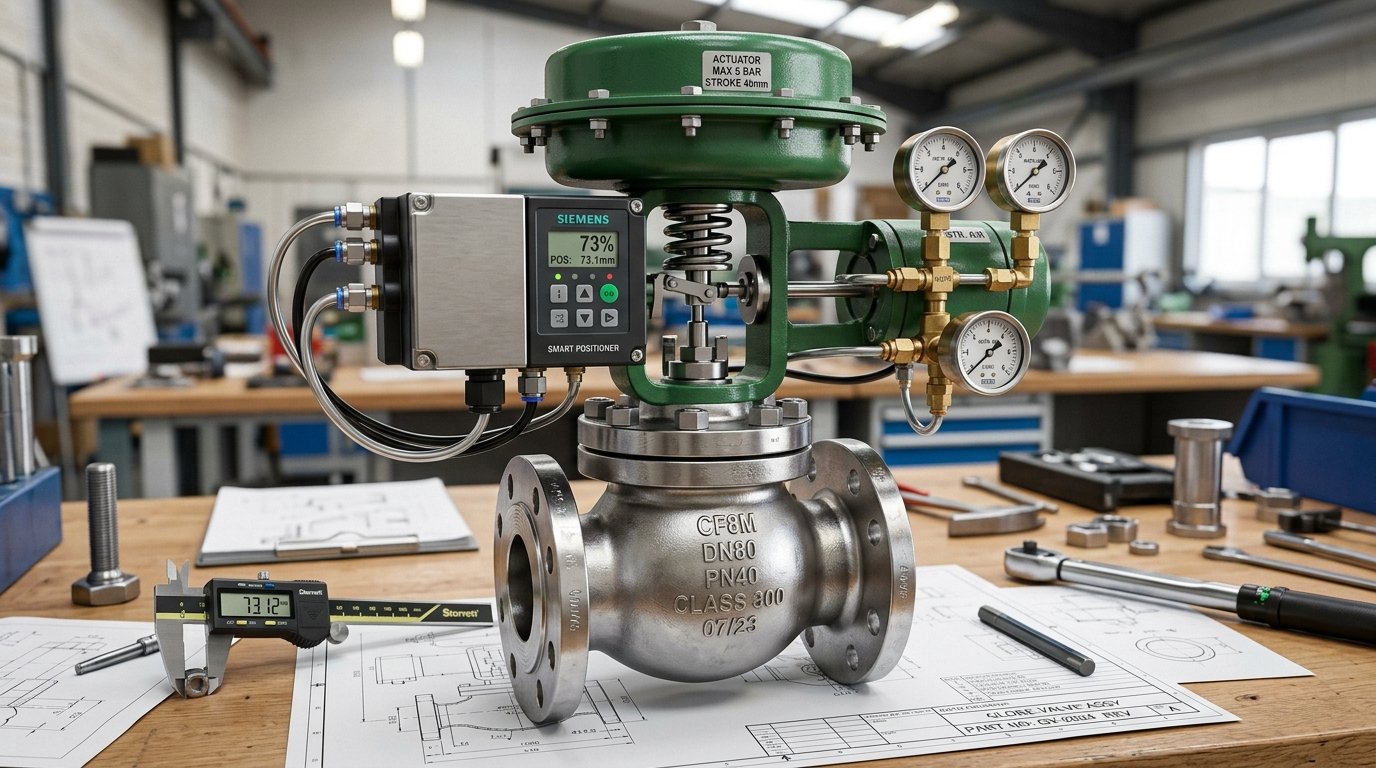
2. Fluid Dynamics: Vena Contracta & Liquid Pressure Recovery Factor (FL)
As process fluid traverses the variable orifice between the valve plug and seat ring, flow velocity reaches an absolute maximum, transforming static pressure into kinetic energy per Bernoulli's conservation theorem. The physical point of minimum cross-sectional flow area and minimum static pressure is designated as the vena contracta (Pvc). Downstream of the vena contracta, fluid expands into the valve outlet gallery, dissipating turbulent kinetic energy and recovering a portion of static pressure to outlet level P2.
The magnitude of pressure recovery is quantified by the dimensionless Liquid Pressure Recovery Factor (FL), defined mathematically as:
• Globe Valves with tortuous cage paths: F_L = 0.85 to 0.95 (High recovery resistance, less prone to deep vena contracta drop)
• Rotary Ball & Butterfly Valves: F_L = 0.55 to 0.70 (Streamlined recovery, high pressure drop concentration, extreme cavitation vulnerability)
3. Liquid Sizing Equations: Standard & Choked Cavitation Regimes
Under non-vaporizing, fully turbulent conditions where pipe diameter equals valve nominal size (no line reducers), the required valve flow coefficient Cv is governed by:
Where:
• Q = Volumetric flow rate (m³/h when N1 = 0.865; gpm when N1 = 1.0)
• Gf = Liquid specific gravity relative to water at 15.6°C (60°F)
• P1, P2 = Static upstream and downstream pressures in absolute units (bar a or psia)
• N1 = Unit numerical constant (0.865 for metric m³/h and bar; 1.0 for US gpm and psi)
When the actual differential pressure ΔP = P1 - P2 surpasses the terminal critical pressure drop ΔPmax, fluid vaporizes into microscopic cavitation bubbles at the vena contracta. Increasing downstream pressure drop further yields zero additional flow: the valve reaches choked flow. Under choked conditions, IEC 60534 dictates substituting ΔPmax into the equation:
F_F = 0.96 - 0.28 * sqrt( Pv / Pc )
Where:
• F_F = Liquid critical pressure ratio factor (dimensionless)
• Pv = Vapor pressure of the liquid at inlet operating temperature
• Pc = Thermodynamic critical pressure of the liquid (e.g., 220.6 bar a for water)
4. Piping Geometry Factor (Fp) and Reducer Head Loss Derivation
In process piping design, installing a 2" control valve in a 4" process line with concentric reducers is standard practice to optimize controllability. However, reducers and expanders introduce entrance head loss and exit sudden expansion loss, reducing effective flow capacity by 5% to 18%. IEC 60534-2-1 Clause 5.2 establishes the Piping Geometry Factor (Fp):
Where:
• Σζ = Sum of piping fitting resistance coefficients = ζ1 (inlet reducer) + ζ2 (outlet expander) + ζ_B1 + ζ_B2
• Inlet reducer loss: ζ1 = 0.5 * [ 1 - (d / D1)² ]²
• Outlet expander loss: ζ2 = 1.0 * [ 1 - (d / D2)² ]²
• d = Nominal control valve internal diameter (mm)
• D1, D2 = Upstream and downstream pipe internal diameters (mm)
• N2 = Numerical constant (0.00214 for metric mm and bar)
5. Compressible Fluids: Gas, Vapor, and Superheated Steam Sizing
For gases and vapors, fluid density decreases continuously along the trim throttling path. IEC 60534-2-1 introduces the Expansion Factor (Y) and the Terminal Pressure Drop Ratio Factor (xT):
Y = 1 - ( x / (3 * Fγ * x_T) )
Where:
• W = Mass flow rate (kg/h)
• x = Operating pressure drop ratio = (P1 - P2) / P1
• x_T = Pressure drop ratio factor at choked flow (typically 0.70 to 0.75 for cage-guided globe trims)
• Fγ = Ratio of specific heats factor = γ / 1.40 (where γ = Cp / Cv)
• Y = Expansion factor (constrained strictly to 0.667 ≤ Y ≤ 1.000)
• Choked Transition Point: When x ≥ Fγ * x_T, sonic velocity (Mach 1.0) is achieved at the vena contracta.
6. Comprehensive Multi-Standard Parameter Matrix
| Engineering Parameter | IEC 60534-2-1 (ISO) | ISA-75.01.01 (ANSI) | Standard Globe Cage | High-Performance Butterfly |
|---|---|---|---|---|
| Flow Coefficient Unit | Kv (m³/h @ ΔP=1 bar) | Cv (US gpm @ ΔP=1 psi) | Cv = 1.156 * Kv | Cv = 1.156 * Kv |
| Liquid Recovery Factor (FL) | F_L | F_L | 0.88 – 0.94 | 0.58 – 0.68 |
| Gas Choked Ratio (xT) | x_T | x_T | 0.72 – 0.78 | 0.30 – 0.40 |
| Vena Contracta Cavitation | Critical ΔP_max | Choked ΔP_choked | High Resistance | Severe Vulnerability |
| Installed Rangeability | 30:1 to 50:1 | 30:1 to 50:1 | 50:1 (Equal %) | 20:1 (Non-linear) |
7. Worked EPC Engineering Calculation: Supercritical Boiler Feedwater
To demonstrate rigorous application, consider a 660 MW thermal power plant high-pressure boiler feedwater bypass control valve with the following process datasheet parameters:
| Process Parameter | Design Input | Unit | Physical Reference |
|---|---|---|---|
| Operating Fluid | Demineralized Boiler Feedwater | — | T = 165°C (329°F) |
| Upstream Pressure (P1) | 48.0 | bar a | Multi-stage feed pump discharge header |
| Downstream Pressure (P2) | 16.0 | bar a | Deaerator / startup drum operating pressure |
| Design Flow Capacity (Q) | 185.0 | m³/h | Maximum continuous rating (110% MCR) |
| Water Vapor Pressure (Pv) | 7.01 | bar a | Steam tables @ 165°C |
| Thermodynamic Critical Pressure (Pc) | 220.64 | bar a | Water critical state |
| Liquid Specific Gravity (Gf) | 0.908 | — | Density = 908 kg/m³ @ 165°C |
| Valve Selected Trim Type | TSV Series 8000 Multi-Stage Cage | — | F_L = 0.92 |
Step 1: Evaluation of Choked Cavitation Limit (ΔPmax)
ΔP_max = (0.92)² * [ 48.0 - (0.9101 * 7.01) ] = 0.8464 * [ 48.0 - 6.38 ] = 0.8464 * 41.62 = 35.23 bar
The actual operating pressure drop is ΔP = 48.0 - 16.0 = 32.0 bar. Because actual ΔP (32.0 bar) < ΔPmax (35.23 bar), the flow regime operates in the non-choked turbulent zone. However, the cavitation index σ = (P1 - Pv) / (P1 - P2) = (48.0 - 7.01) / 32.0 = 1.28, which is well below the incipient damage threshold (σ < 1.50). Standard single-stage trim would suffer destructive micro-jet pitting within 500 operating hours. A TSV 3-Stage Anti-Cavitation Labyrinth Cage Trim is mandated.
Step 2: Effective Operating Cv Calculation
To guarantee stable loop authority without operating near stroke extremes, EPC specification mandates sizing the valve such that normal operating Cv falls between 60% and 75% of rated full-open Cv. Sizing Cv,rated = 36.03 / 0.70 ≈ 51.5 Cv. We specify a TSV 3" Class 600 ASME B16.34 Equal-Percentage Globe Control Valve (Rated Cv = 54.0), operating at precisely 71.4% stroke under maximum load, perfectly centered in the linear controllability corridor.
8. Aerodynamic Noise Prediction & Mach Velocity Control per IEC 60534-8-3
When high-pressure gas or steam experiences sonic velocity at the vena contracta, acoustic shockwaves radiate through the valve body and pipe wall. Under IEC 60534-8-3, aerodynamic noise is controlled through velocity limitation rather than heavy acoustic blankets:
Outlet Gallery Mach Limit: Ma_outlet ≤ 0.35 (continuous duty) / Ma_outlet ≤ 0.50 (intermittent relief)
Downstream Expanded Pipe: Ma_pipe ≤ 0.20
9. Three Critical EPC Sizing Pitfalls & Mitigation SOP
- Over-Conservatism Stacking (The "Double 120%" Trap): Process engineers specify 120% flow; mechanical engineers specify a valve with an additional 130% margin. The installed valve operates at 8% stroke, resulting in severe seat wire-drawing and positioner hunting. Always size against real pump curves.
- Neglecting Body Galloping Velocity in Flashing Streams: When liquid flashes into vapor (P2 < Pv), volumetric flow expands by up to 200 times. An angle valve body discharging directly into an expanded pipe with hardened Stellite 6 trim is mandatory to prevent body wall erosion.
- Unbalanced Actuator Thrust Margin: Failing to include unbalance force at full shutoff ΔP, packing friction, and seat loading per FCI 70-2 Class V (up to 300 lb/linear inch) leads to actuator stall and seat passing. Always apply an actuator thrust safety factor ≥ 1.35.
10. Frequently Asked Engineering Questions (Technical FAQ)
Kv is the metric flow coefficient defined as cubic meters per hour (m³/h) of water at 5°C to 40°C with a pressure drop of 1 bar. Cv is the imperial coefficient defined as US gallons per minute (gpm) of water at 60°F with a pressure drop of 1 psi. The exact conversion factor is Cv = 1.156 * Kv (or Kv = 0.865 * Cv).
Reducers introduce abrupt contractions and expansions that reduce the available pressure drop at the valve orifice. Ignoring the piping geometry factor Fp results in an undersized valve that starves the process when flow reaches design capacity.
TSV Series 8000 multi-stage trim divides the overall differential pressure ΔP across multiple concentric tortuous-path chambers. By distributing the pressure reduction into 3 to 6 stages, the static pressure in each individual chamber never drops below the liquid vapor pressure Pv, preventing vapor bubble formation entirely.
Related TSV Engineering Resources:
- TSV Heavy-Duty Globe & Cage-Guided Control Valves Line
- Multi-Stage Anti-Cavitation Cage Guided Control Valves
- Interactive IEC 60534 Cv / Kv Flow Sizing Calculator
- Centrifugal Compressor Anti-Surge Control Valve Engineering
- Cavitation vs. Flashing: Multi-Stage Trim Geometries and Metallurgy
Need Technical Engineering Consultation or Sizing Verification?
Connect directly with TSV Application Engineering Desk for valve sizing, NACE compliance audits, and custom severe-service trim design.