
1. Wet H₂S Cracking Physics: Environmental Cracking Mechanisms
In upstream oil and gas production, refining, and sour gas processing facilities, fluid streams containing hydrogen sulfide (\(H_2S\)) in the presence of free water represent the most lethal corrosive environment encountered in chemical and piping engineering. Wet \(H_2S\) reacts with bare steel to form iron sulfide and liberate atomic hydrogen:
Under ordinary conditions, atomic hydrogen recombines into harmless molecular hydrogen (H₂). In sour environments, however, sulfide ions act as a surface poison that blocks recombination. The nascent atomic hydrogen (H) diffuses freely into the steel's interstitial crystal lattice, triggering four distinct metallurgical failure mechanisms:
- Sulfide Stress Cracking (SSC): Catastrophic brittle failure of high-strength or hardened steels under simultaneous tensile stress and hydrogen embrittlement. SSC can cause sudden, catastrophic rupture of valve body bolts, stems, and bonnet flanges within hours of exposure without prior warning or visible metal loss.
- Hydrogen-Induced Cracking (HIC): Atomic hydrogen diffuses into internal steel voids and non-metallic planar inclusions (such as manganese sulfides, MnS). Hydrogen atoms recombine into molecular \(H_2\) gas inside internal laminations, generating extreme internal pressures exceeding 1,000 bar. This causes internal planar delaminations and external surface blistering.
- Stress-Oriented Hydrogen-Induced Cracking (SOHIC): Small internal HIC cracks align perpendicularly under high hoop stresses, linking together into a through-wall staircase crack that leads to catastrophic pipe and body wall perforation.
- Galvanic & Stress Corrosion Cracking (SCC): Accelerated cracking of austenitic and duplex stainless steels in hot sour brine containing both \(H_2S\) and chlorides (\(Cl^-\)).
2. NACE MR0175 / ISO 15156 Environmental Severity Mapping
Standard NACE MR0175 / ISO 15156 ("Petroleum and natural gas industries — Materials for use in H2S-containing environments in oil and gas production") establishes three distinct parts:
- Part 1: General principles for selection of cracking-resistant materials.
- Part 2: Cracking-resistant carbon and low-alloy steels and the use of cast irons.
- Part 3: Cracking-resistant CRAs (Corrosion-Resistant Alloys) and other alloys.
For carbon and low-alloy steels, Part 2 divides sour service environments into four SSC Regions of Environmental Severity based on in-situ pH and \(H_2S\) partial pressure (\(P_{H2S}\)):
| SSC Severity Region | H₂S Partial Pressure (P_H2S) | In-Situ Process pH | Metallurgical & Testing Qualification Requirements |
|---|---|---|---|
| Region 0 (Non-Sour) | P_H2S < 0.05 psia (0.3 kPa) | Any pH | Standard ASME B16.34 materials acceptable; no mandatory NACE restrictions. |
| Region 1 (Low Sour Severity) | P_H2S ≥ 0.05 psia | pH ≥ 5.5 | Base hardness limits apply (22 HRC max); standard heat treatment. |
| Region 2 (Intermediate Sour Severity) | P_H2S ≥ 0.05 psia | 3.5 < pH < 5.5 | Strict 22 HRC hardness limits; mandatory PWHT of all welds; HIC testing recommended. |
| Region 3 (Severe Sour Service) | P_H2S ≥ 0.05 psia | pH ≤ 3.5 | Full SSC qualification per NACE TM0177 Method A/D; mandatory HIC testing per TM0284; CRA weld overlay required for dynamic seals. |
3. Carbon and Low-Alloy Steels Hardness Thresholds: The 22 HRC Ceiling
The cornerstone mandate of NACE MR0175 Part 2 is the universal hardness ceiling of 22 HRC (250 HBW / 250 HV) for carbon and low-alloy steels (including ASTM A105, A216 WCB/WCC, A350 LF2, and A352 LCC/LCB):
• Base Metal Maximum Hardness: ≤ 22 HRC (Rockwell C scale) or ≤ 250 HBW.
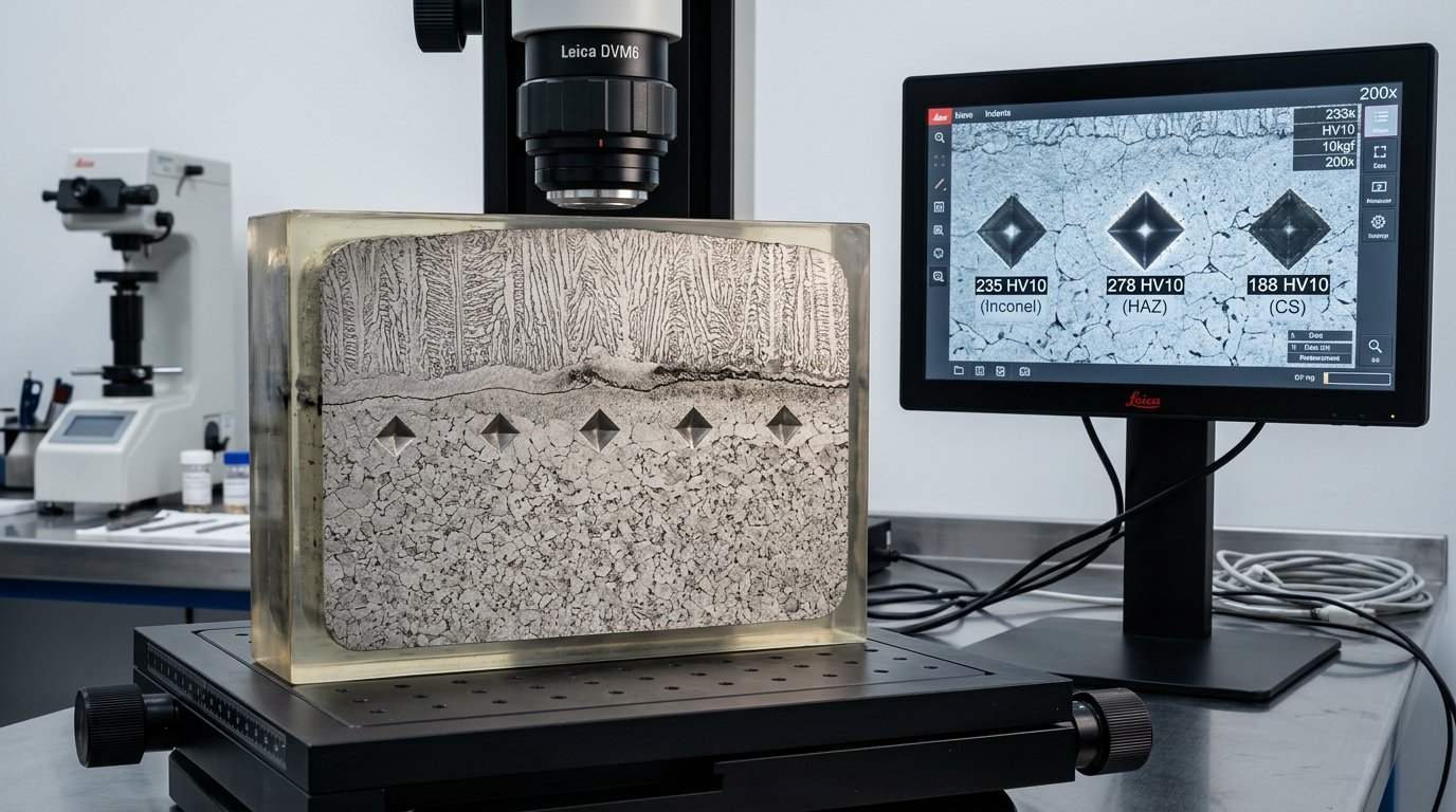
• Weld Metal Maximum Hardness: ≤ 22 HRC (250 HV10).
• Weld Heat Affected Zone (HAZ) Maximum Hardness: ≤ 22 HRC (250 HV10).
• Fasteners & Bolting (Exposed): ASTM A193 Gr. B7M (≤ 235 HBW / 22 HRC) or ASTM A320 Gr. L7M. Standard B7/L7 bolts are strictly banned from sour exposure!
4. Chemical Composition Restrictions & Clean Steel Chemistry
To resist HIC and SOHIC, carbon steels destined for sour service must adhere to strict compositional limits:
- Nickel Content Restriction: Carbon and low-alloy steels must contain a maximum of 1.00 wt% Nickel (\(Ni \le 1.00\%\)). Elevated nickel content promotes martensite formation and micro-segregation, drastically accelerating sulfide stress cracking susceptibility.
- Ultra-Low Sulfur & Phosphorus: To eliminate planar manganese sulfide (MnS) stringers that trigger HIC, sour service steels must be calcium-treated for inclusion shape control with Sulfur \(S \le 0.002\ wt\%\) and Phosphorus \(P \le 0.010\ wt\%\).
- Carbon Equivalent (CE) Control: Restricting weldability hardness spikes by capping:
CE_{IIW} = C + Mn/6 + (Cr+Mo+V)/5 + (Ni+Cu)/15 ≤ 0.43%
5. Post-Weld Heat Treatment (PWHT) & Residual Stress Relief
Welding creates severe untempered martensite and localized tensile residual stresses approaching yield strength in the Heat Affected Zone (HAZ). Under NACE MR0175 Part 2, mandatory Post-Weld Heat Treatment (PWHT) is required for all welded pressure boundaries and structural attachment welds, regardless of nominal pipe thickness, to temper the HAZ microstructure and reduce hardness below the 250 HV10 limit.
6. Corrosion Resistant Alloys (CRAs) in Severe Sour Service
When high temperatures, elevated \(H_2S\) concentrations, or high chloride contents exceed the limits of carbon steel, engineers must select Corrosion Resistant Alloys governed by NACE MR0175 / ISO 15156 Part 3:
| Alloy Category | Standard Valve Alloys | Maximum H₂S Partial Pressure | Max Operating Temp | Hardness Ceiling & Environmental Limits |
|---|---|---|---|---|
| Austenitic Stainless | 316 / 316L (UNS S31603) | P_H2S ≤ 1.5 psia (10 kPa) | 60 °C (140 °F) if Cl⁻ > 1,000 mg/L | 22 HRC max; solution annealed condition. High risk of SCC at elevated temperatures. |
| 22Cr Standard Duplex | 2205 (UNS S31803 / S32205) | P_H2S ≤ 4.4 psia (30 kPa) | 232 °C (450 °F) | 28 HRC max; ferrite content 35% – 65%. Solution annealed and water quenched. |
| 25Cr Super Duplex | 2507 (UNS S32750 / S32760) | P_H2S ≤ 4.4 psia (30 kPa) | 232 °C (450 °F) | 32 HRC max; Pitting Resistance Equivalent Number PRE_N ≥ 40.0. |
| Solid Inconel 625 | Alloy 625 (UNS N06625) | No H₂S limit in Part 3 Table A.13 | 232 °C (450 °F) | 35 HRC max; exceptional resistance to sour brine and elemental sulfur. |
| High-Strength Trim | Inconel 718 (UNS N07718) | No H₂S limit in Part 3 Table A.13 | 232 °C (450 °F) | 40 HRC max; industry standard for high-strength sour service valve stems. |
7. Inconel 625 Weld Overlay Metallurgy (Cladding)
Forging massive valve bodies out of solid Inconel 625 or Super Duplex is cost-prohibitive for large-diameter pipeline valves (16" to 36" Class 600–2500). The globally accepted EPC engineering standard is a carbon steel forged body (A350 LF2 / A105) lined with an automated hot-wire TIG weld overlay of Inconel 625:
- Overlay Thickness: Minimum 3.0 mm finished thickness after machining on all wetted surfaces, seat pockets, dynamic stem bores, and ring joint (RTJ) grooves.
- Iron Dilution Control: Iron migration from the carbon steel base metal into the overlay degrades corrosion resistance. Automated welding procedures must guarantee Iron Dilution \(Fe \le 5.0\ wt\%\) in the top 2.0 mm layer.
8. Laboratory Qualification Testing: NACE TM0177 & TM0284
Mandatory Verification Testing Dossier:
- NACE TM0177 Method A (Uniaxial Tensile Test): Specimens loaded to 80% of actual yield strength immersed in acidified sour brine (5% NaCl, 0.5% glacial acetic acid, saturated with 100% \(H_2S\) at 1 bar) for 720 hours (30 days) without failure or micro-cracking.
- NACE TM0284 (HIC Testing): Three specimens from each casting/forging heat immersed in Solution A for 96 hours. Metallographic evaluation must satisfy:
- Crack Sensitivity Ratio: \(CSR \le 0.5\%\)
- Crack Length Ratio: \(CLR \le 1.5\%\)
- Crack Thickness Ratio: \(CTR \le 0.5\%\)
- 100% Hardness Verification: Portable ultrasonic contact impedance (UCI) or Rockwell hardness testing on every finished valve body and bonnet.
Only if the bolting is completely protected from the atmosphere or buried/insulated without potential exposure to H₂S leaks. In offshore and sour plant facilities, exposed bolting must be ASTM A193 Grade B7M (or A320 L7M) with a mandatory hardness ceiling of 22 HRC (235 HBW maximum) to prevent catastrophic environmental cracking.
Extensive metallurgical research demonstrated that nickel concentrations above 1.0 wt% in carbon steels accelerate hydrogen diffusion kinetics and promote localized martensitic micro-segregation, significantly reducing the steel's threshold stress intensity for sulfide stress cracking (K_ISSC).
The manufacturer must provide an EN 10204 Type 3.1 Material Test Report (MTR) explicitly citing NACE MR0175/ISO 15156 compliance, reporting actual chemical composition (verifying Ni ≤ 1.0%, S ≤ 0.002%), actual heat treatment cycle and PWHT temperatures, actual hardness values (≤ 22 HRC), and NACE TM0284 HIC test certificates.
Related TSV Engineering Resources:
- TSV API 6D Forged & Cast Trunnion Ball Valves for Sour Service
- EN 10204 3.1 & 3.2 Material Inspection Protocols
- API 6D & CE PED Factory Quality Certifications
- Factory 100% Pressure Testing SOP per API 598 & ISO 5208
- Valve Fugitive Emissions Standards: ISO 15848-1 vs. API 641
Need Technical Engineering Consultation or Sizing Verification?
Connect directly with TSV Application Engineering Desk for valve sizing, NACE compliance audits, and custom severe-service trim design.