
1. The Phenomenon of Control Valve Jerking: Limit Cycling vs. Process Sensor Oscillation
In automated process plants, a control valve that exhibits erratic jumping, stepped movement, or continuous oscillation—commonly called valve hunting or jerking—degrades loop control performance, causes product off-spec excursions, and accelerates packing gland and trim failure. In severe cases, rapid cycling (10 to 40 movements per minute) damages positioner linkages, work-hardens actuator diaphragms, and destroys stem packings within weeks. Field diagnostic investigations reveal that over 70% of hunting valves suffer from stick-slip friction or positioner-actuator pneumatic tuning mismatches rather than tuning errors in the Distributed Control System (DCS).
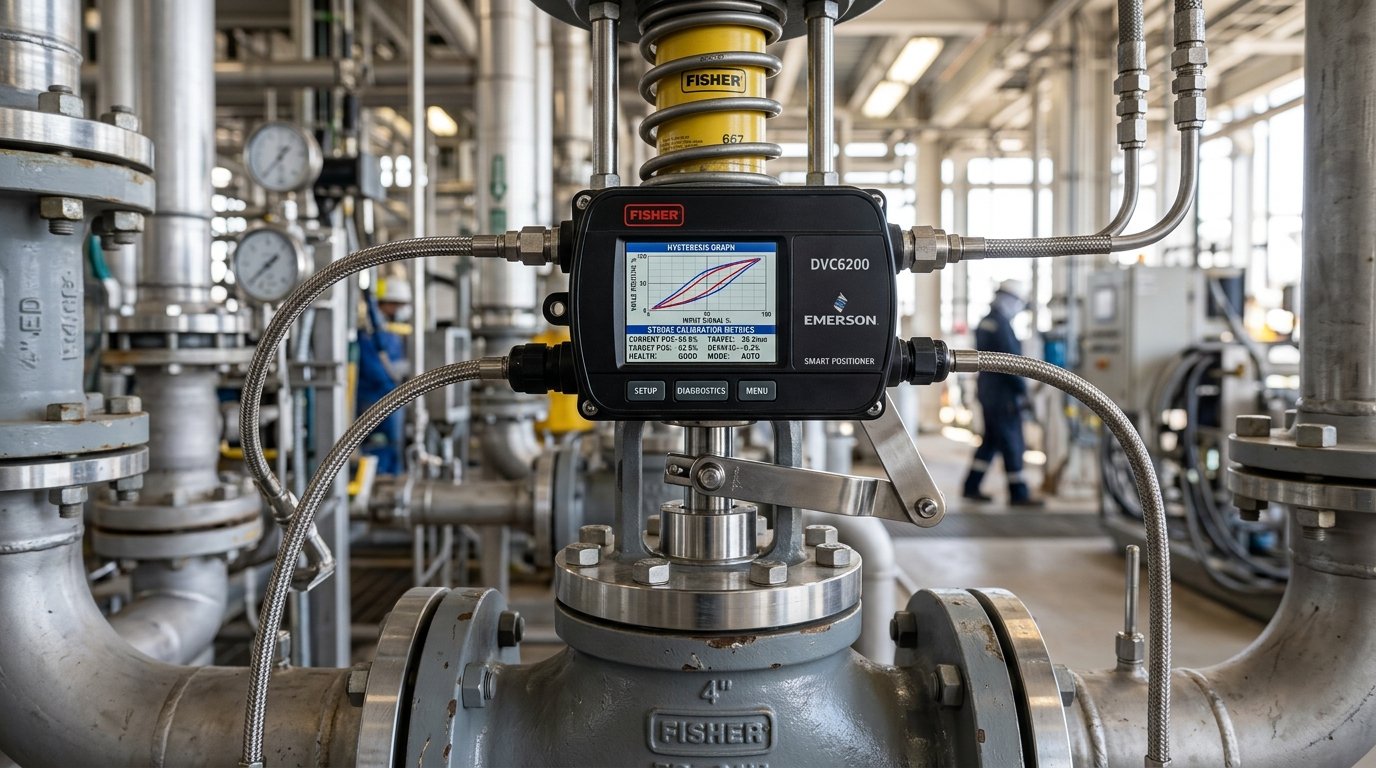
2. Physics of Stick-Slip: Static Friction (μs) vs. Dynamic Friction (μk)
The core physical mechanism driving control valve jerking is the disparity between static friction (breakaway friction, μs) and dynamic sliding friction (μk) within the stem packing gland and guide bushings:
1. The positioner increases air pressure in the actuator cylinder to initiate a small 1% stroke change.
2. Because static friction F_static is high, the stem remains stuck in place.
3. The positioner continues integrating error, building higher and higher actuator pressure.
4. Once actuator force finally exceeds F_static, the stem breaks free.
5. The moment motion begins, friction instantly drops to the lower dynamic level F_dynamic.
6. The excess stored pneumatic energy causes the valve to violently jerk past the target setpoint.
7. The positioner attempts to correct in the reverse direction, triggering an endless limit-cycle oscillation.
3. Quantifying Deadband and Hysteresis per ISA-75.05.01
| Control Valve Metric | Acceptable High-Performance Level | Marginal / Acceptable Level | Severe Problem (Immediate SOP Required) |
|---|---|---|---|
| Total Deadband | < 0.2% of span | 0.2% to 0.8% of span | > 1.5% of span |
| Hysteresis | < 0.3% of span | 0.3% to 1.0% of span | > 2.0% of span |
| Step Response Time (2% step) | T86 < 1.2 seconds | 1.2 to 3.0 seconds | > 5.0 seconds (Sluggish) |
| Overshoot on Small Step | < 5% of step | 5% to 15% of step | > 25% (Under-damped hunting) |
4. Diagnostic Decision Tree: Isolating DCS Loop vs. Valve Mechanics
- Step 1: Put DCS Loop in Manual: Switch controller mode from Auto to Manual. If the oscillation ceases completely and the valve holds steady, the root cause is DCS PID loop over-tuning (excessive integral gain or dead time). If the valve continues to jump or hunt in manual mode, the fault is 100% inside the valve/positioner assembly.
- Step 2: Disconnect Positioner Feedback Arm: Inspect the mechanical positioner feedback linkage for loose screws, worn pivot bearings, or bent levers. Even 0.5 mm of linkage backlash translates to 1.5% actuator deadband.
- Step 3: Perform Multi-Step Signal Tests: Inject step inputs of 0.5%, 1.0%, 2.0%, and 5.0%. If the valve responds cleanly to 5.0% steps but refuses to move for 1.0% steps, excessive packing stiction is confirmed.
5. Smart Positioner Diagnostic Signature Analysis
Modern digital smart positioners (such as HART / Foundation Fieldbus units fitted on TSV valves) record online dynamic actuator pressure vs. valve travel curves. High packing friction appears clearly as a wide horizontal pressure hysteresis band before travel commences.
6. Live-Loaded Stem Packing: Belleville Spring Stack Calculation
To eliminate stick-slip while maintaining fugitive emission sealing compliance under ISO 15848-1 / API 641, TSV specifies Live-Loaded Packing Glands incorporating precision Belleville disc spring washers:
• Pre-compression: Springs are torqued to 80% of flat deflection to maintain constant seal stress (approx. 25 to 35 MPa on graphite rings).
• Thermal Compensation: As graphite packing consolidates over thousands of thermal cycles, disc springs expand, preventing gland relaxation without requiring over-tightening.
7. Field Troubleshooting SOP: Step-by-Step Remediation Checklist
| Troubleshooting Step | Action Items & Verification | Target Outcome |
|---|---|---|
| 1. Instrument Air Supply Check | Verify supply pressure is stable at ±0.2 bar; check filter-regulator for liquid water, oil mist, or particulate clogging. | Stable clean air supply to positioner |
| 2. Feedback Linkage Inspection | Tighten all mounting bracket bolts; verify magnetic or slotted pin has zero play across 0–100% stroke. | Zero mechanical backlash (< 0.05 mm) |
| 3. Positioner Auto-Tuning | Initiate digital positioner auto-calibration routine; verify pneumatic booster bypass needle valve is tuned properly. | Optimal damping coefficient without hunting |
| 4. Packing Gland Relaxation | Loosen gland flange nuts slightly; re-torque evenly in cross pattern using calibrated torque wrench to manufacturer live-load specs. | Stiction reduced by 40% to 60% |
| 5. Spool / Relay Cleaning | Remove positioner I/P converter or pneumatic spool valve; clean flapper-nozzle orifice using alcohol spray. | Eliminate pneumatic relay hysteresis |
8. Frequently Asked Engineering Questions (Technical FAQ)
Put the loop into Manual mode. If the oscillation immediately stops, the problem is DCS tuning (excessive controller gain). If the valve continues to jump or cannot be set to an exact stroke value, the issue is valve packing stiction or positioner feedback backlash.
Die-formed flexible graphite requires much higher compressive gland loading (30–45 MPa) to seal against fugitive emissions compared to virgin PTFE (10–15 MPa). Graphite also exhibits a higher coefficient of static friction, increasing breakaway force unless live-loaded Belleville springs and ultra-smooth stem finishes (Ra < 0.2 μm) are utilized.
If the internal bypass needle valve on a volume booster is closed too far, the booster activates even for tiny 0.5% positioner adjustments, injecting excessive air volume and causing severe overshoot and limit cycling. Opening the bypass needle valve dampens small corrections while retaining high-speed stroke capability for large steps.
Related TSV Engineering Resources:
- TSV Heavy-Duty Globe & Cage-Guided Control Valves Line
- Factory 100% Pressure Testing SOP per API 598 & ISO 5208
- Interactive Valve Selection Decision Matrix
- EN 10204 3.1 & 3.2 Inspection Protocols
- Control Valve Sizing Guide per IEC 60534-2-1
Need Technical Engineering Consultation or Sizing Verification?
Connect directly with TSV Application Engineering Desk for valve sizing, NACE compliance audits, and custom severe-service trim design.